Steven's APT Station
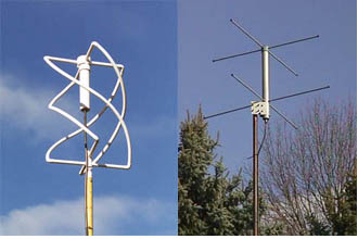
Typical APT weather satellite ground station configuration.
.jpg)
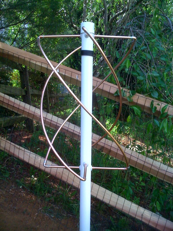
MY home built APT antenna
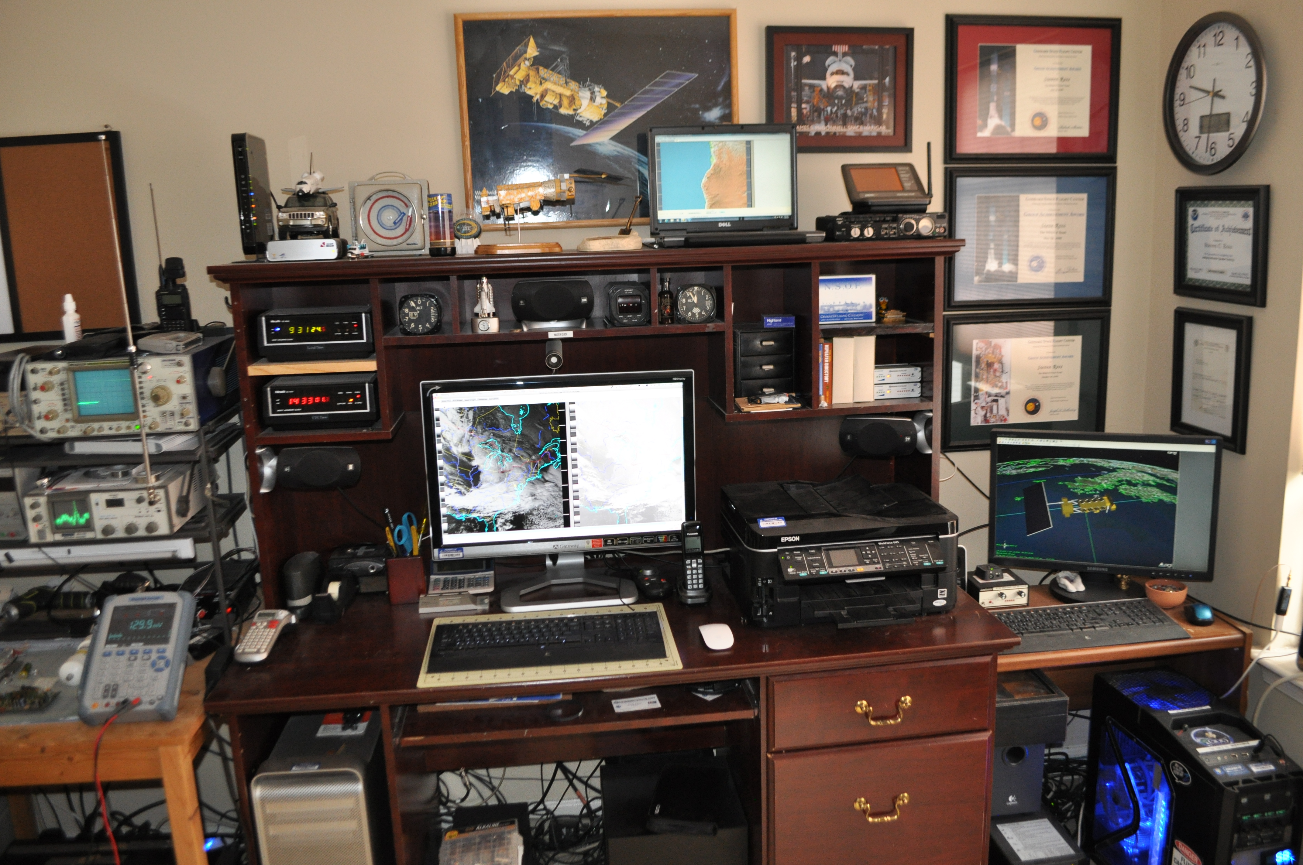
My APT Station
The APT Signal is transmitted from one of 4 passing NOAA weather satellites which is received by my custom built Quadrifilar antenna. The antenna is connected with coax feedline to an R2FX APT receiver. Demodulated audio from the receiver is connected to the audio input of my Mac Pro. Audio from my receiver is processed using WXtoImg, saved on my computer's hard drive as a wave file. The software then processes the wave file and converts it to an image. The image is then overlaid with a map and text, then uploaded to the website.
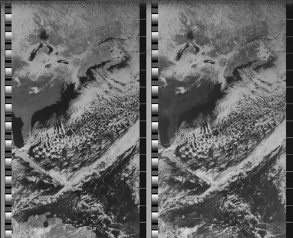
APT Trasmission Format
The trasmission includes a series of synchronization pulses, minute markers, and telemetry information.
The synchronization information, transmitted at the start of each video channel, allows the receiving software to align its sampling with the baud rate of the signal, which can vary slightly over time. The minute markers are four lines of alternating black then white lines which repeat every 60 seconds (120 lines).
The telemetry section is composed of sixteen blocks, each 8 lines long, which are used as reference values to decode the image channels. The first eight blocks, called "wedges," begin at 1/8th max intensity and successively increase by 1/8th to full intensity in the eighth wedge, with the ninth being zero intensity. Blocks ten through fifteen each encode a calibration value for the sensor. The sixteenth block identifies which sensor channel was used for the preceding image channel by matching the intensity of one of the wedges one through six. Video channel A typically matches either wedge two or three, channel B matches wedge four.
The first fourteen blocks should be identical for both channels. The sixteen telemetry blocks repeat every 128 lines, and these 128 lines are referred to as a frame.